

Edging Techniques for Ultra-Thin Metal Strips
Comments Off on Edging Techniques for Ultra-Thin Metal Strips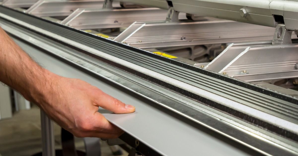
Ultra-thin metal strips can support precise applications in aerospace, medical, stamping, chemical etching, and other demanding industries. Yet thin material requires careful handling from processing through final fabrication. Edge condition plays an important role because even small imperfections can affect handling, fit, and downstream performance.
Manufacturers use edging techniques for ultra-thin metal strips to refine strip edges after slitting or other processing steps. The right approach depends on the alloy, thickness, application, and edge profile.
Why Edge Condition Matters in Thin Metal
Ultra-thin strip reacts differently than heavier material during processing. Burrs, sharp edges, or inconsistent profiles can create problems during stamping, forming, assembly, or other precision operations.
A controlled edge can improve handling and help the material move more consistently through downstream equipment. It can also support tighter dimensional requirements when manufacturers need repeatable results from one production run to the next.
Common Edging Techniques for Thin Metal Strip
A qualified sheet metal supplier may use several edging methods depending on the material and customer specifications. Each technique changes the edge in a different way, so manufacturers should select the process with the application in mind.
Deburring
Deburring removes sharp projections or raised material left along an edge after cutting or slitting. With ultra-thin strip, processors must control this step carefully because excessive pressure can distort the material.
A deburred edge can improve handling and reduce interference during later manufacturing steps. The process works best when the processor matches the equipment and settings to the metal’s thickness, hardness, and alloy.
Rounded Edging
Another edging technique for ultra-thin metal strips is rounded edging. Rounded edging creates a smoother, curved profile instead of leaving a sharp corner. This edge style can make thin strips easier to handle and may suit applications that involve frequent movement, contact, or assembly.
Processors need precise control when forming a rounded edge on very thin material. Too much force can affect flatness or change the dimensions of the strip.
Square and Controlled Edge Profiles
Some applications require a more defined edge rather than a rounded finish. In these cases, processors can maintain a square or specified profile while controlling burrs and edge consistency.
This approach can support precision parts where edge geometry affects fit or later processing. Manufacturers should clearly communicate tolerances and application requirements before production begins.
Choosing the Right Edging Method
The best edging technique depends on several factors, including alloy type, strip thickness, hardness, dimensional tolerances, and the manufacturing process. Stainless steel, aluminum, copper, and brass can respond differently to cutting, slitting, and edge finishing.
Manufacturers should also consider how the strip will move through their own equipment. An edge that works well for one stamping or forming process may not suit another, particularly when the material becomes extremely thin.
Start With the Right Edge
Edge preparation can make a meaningful difference in how ultra-thin metal strip performs during fabrication and assembly. By matching the edging method to the material, dimensions, and application, manufacturers can support cleaner processing and more consistent results.
Thin Metal Sales provides custom slit-to-width and cut-to-length metal products in stainless steel, aluminum, copper, and brass. Contact Thin Metal Sales to discuss your material requirements, edge specifications, and next thin metal project.
Thin Stainless for Wearable Medical Sensors
Comments Off on Thin Stainless for Wearable Medical Sensors
Wearable medical sensors must perform while users move, exercise, sleep, and complete daily activities. Their internal components require materials that fit into compact designs without sacrificing strength, stability, or manufacturability.
Stainless steel gives engineers a practical option for structural, electrical, and protective components. Manufacturers can process it through chemical etching, laser cutting, waterjet cutting, and precision stamping to create detailed parts for medical applications. Keep reading to understand more about thin stainless steel for wearable medical sensors.
Why Material Thickness Matters in Wearable Devices
Every fraction of an inch matters inside a wearable sensor. A thinner component can help reduce device size, support a lower profile, and leave more room for batteries, circuitry, and sensing elements.
Thickness also affects how a part bends, holds its shape, and responds to repeated movement. Engineers must balance flexibility with the stiffness required to protect delicate electronics or maintain consistent contact with another component.
Supporting Complex Component Designs
Wearable sensors may require springs, shields, contacts, spacers, covers, or precision-formed parts. Thin stainless supports these wearable medical sensor functions while allowing manufacturers to create narrow features and complex geometries.
Consistent material dimensions also help fabricators maintain tighter process control. Stainless steel mills use gauge-control systems to monitor and adjust sheet thickness during production, supporting greater dimensional consistency.
Selecting Thin Sheet Stainless Steel for Sensor Parts
Engineers should select thin sheet stainless steel according to the device’s mechanical requirements, production method, operating conditions, and component function. Stainless steel includes multiple alloy families and grades, so no single option fits every application.
Type 304 remains a widely common austenitic grade across industrial and commercial applications. However, designers should evaluate each grade based on required formability, strength, corrosion resistance, and compatibility with the specific fabrication process.
Matching Material to Fabrication
The production method can shape the material decision. Chemical etching can create intricate, burr-free features, while precision stamping can support higher production volumes and repeatable geometries.
Laser and waterjet cutting provide additional options for prototypes, special shapes, and varying production needs. Engineers can reduce design revisions by involving the material supplier and fabricator early in development.
Surface Finish and Component Performance
Surface finish may influence appearance, contact behavior, bonding, and downstream processing. Designers should specify finish requirements clearly rather than relying on a finish name alone.
Finish appearance can vary between suppliers, lots, and individual pieces. Physical samples can help teams establish a practical visual standard when consistency matters.
Start With the Right Stainless Material
Wearable medical sensors demand compact components, precise dimensions, and dependable material performance. Thin stainless gives product teams the versatility to design parts that support small, durable, and production-ready devices.
Contact Thin Metal Sales to discuss stainless steel grades, thickness requirements, custom widths, and cut-to-length options for your next wearable medical sensor application.
Copper Sheets for RF Shielding Applications
Comments Off on Copper Sheets for RF Shielding Applications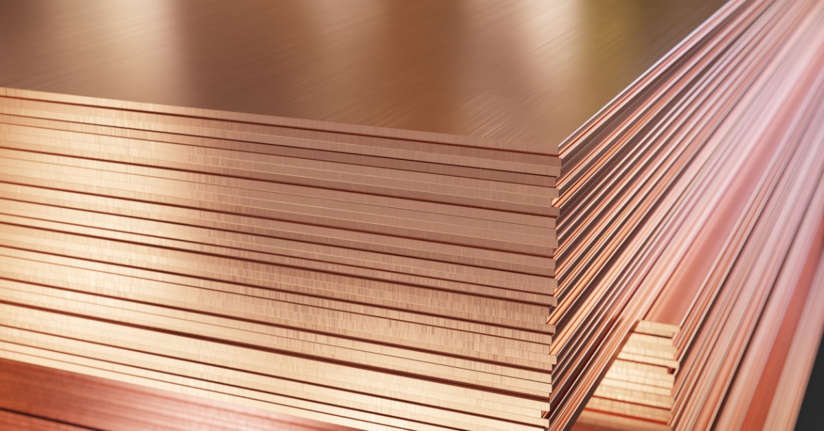
Copper sheets for RF shielding are often specified by alloy and thickness before anyone considers how the finished enclosure will come together. The material may offer excellent conductivity, but if forming creates inconsistent seams or poorly controlled openings, the shield can still underperform where electromagnetic energy can find a path.
The most effective shielding parts aren’t necessarily made from the thickest copper or the highest-conductivity grade. They’re the ones designed with a clear understanding of how the fabricated geometry will affect electrical continuity. That perspective should better guide your evaluation of copper sheet for an RF shielding application.
Treat the Enclosure as an Electrical Boundary
A flat copper panel can attenuate electromagnetic energy effectively, but an enclosure only performs as well as its weakest boundary. Openings for connectors or ventilation interrupt the current path, and their effect depends on the geometry relative to the frequencies involved. You therefore need to evaluate these features as part of the shielding design rather than leaving them as routine secondary operations.
Seams create a similar challenge. Two formed flanges can appear fully closed, yet uneven contact pressure may leave portions of the joint electrically inconsistent. The drawing should identify where reliable metal-to-metal contact is required so the fabricator can protect those surfaces through forming and assembly.
Select Thickness for Forming Behavior, Not Just Attenuation
A thicker sheet won’t compensate for a poorly designed joint. Once the wall provides sufficient attenuation for the application, additional gauge may add stiffness without correcting leakage around openings or seams. Thickness still matters, however, because it affects bend force and dimensional stability after forming.
Thin copper sheets can support compact profiles and detailed features for RF shielding applications, but they may distort when the tooling or bend sequence is poorly matched to the part. Heavier material can hold its shape more readily, although it may complicate tight bends. The useful specification accounts for both the electromagnetic requirement and the geometry that the shop must produce.
Preserve Contact Through Fabrication
The quality of copper sheet metal fabrication is most evident at edges and bends, where small dimensional shifts can alter how adjoining parts meet. A flange that falls outside its intended angle may still pass a basic dimensional check, while creating inconsistent electrical contact across the seam. Flatness and mating geometry deserve explicit tolerances when they influence shielding performance.
Temper selection also affects how the sheet responds during fabrication. A softer condition may form readily, while a harder condition can provide greater stiffness after processing. Neither choice is universally better, so the specification should reflect the bend radius and final assembly method.
Provide the fabricator with more than the outside dimensions. Show the critical contact zones and note any areas where coatings must not interfere with continuity. The drawing should also identify which joints carry the shielding function, allowing the shop to protect them through cutting and forming.