sales@thinmetalSales.comSales@ThinMetalSales.com (909) 393-2273
  • Blog
  • About Us
  • Our Team
  • FAQ
RFQ
Site Logo
Close
  • Blog
  • About Us
  • Our Team
  • FAQ
RFQ
  • Home
  • Products
    • Stainless Steel
    • Copper & Brass
    • Aluminum
  • Technical Information
    • Certifications
    • Prop 65
  • Industries
    • Aerospace
    • Consumer
    • Medical
  • Contact Us
 

Author Archives: Jon

  1. Edging Techniques for Ultra-Thin Metal Strips

    August 31, 2026 8:19 pm Comments Off on Edging Techniques for Ultra-Thin Metal Strips

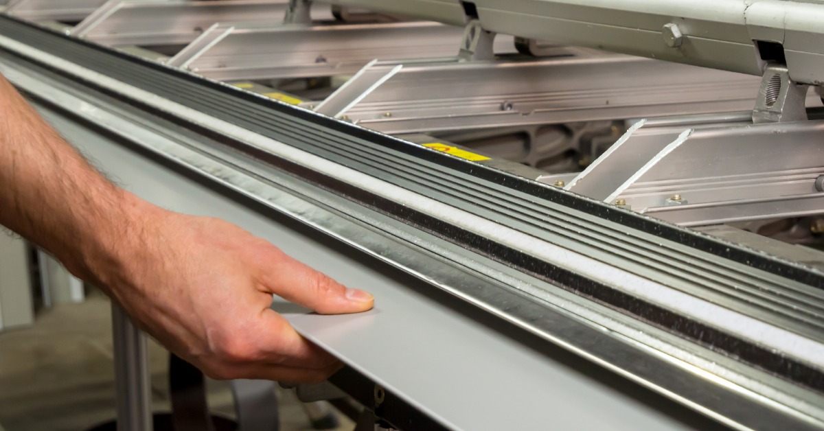
    A close-up of a man's hands holding the edge of a sheet of thin metal as it enters a manual bending machine.

    Ultra-thin metal strips can support precise applications in aerospace, medical, stamping, chemical etching, and other demanding industries. Yet thin material requires careful handling from processing through final fabrication. Edge condition plays an important role because even small imperfections can affect handling, fit, and downstream performance.

    Manufacturers use edging techniques for ultra-thin metal strips to refine strip edges after slitting or other processing steps. The right approach depends on the alloy, thickness, application, and edge profile.

    Why Edge Condition Matters in Thin Metal

    Ultra-thin strip reacts differently than heavier material during processing. Burrs, sharp edges, or inconsistent profiles can create problems during stamping, forming, assembly, or other precision operations.

    A controlled edge can improve handling and help the material move more consistently through downstream equipment. It can also support tighter dimensional requirements when manufacturers need repeatable results from one production run to the next.

    Common Edging Techniques for Thin Metal Strip

    A qualified sheet metal supplier may use several edging methods depending on the material and customer specifications. Each technique changes the edge in a different way, so manufacturers should select the process with the application in mind.

    Deburring

    Deburring removes sharp projections or raised material left along an edge after cutting or slitting. With ultra-thin strip, processors must control this step carefully because excessive pressure can distort the material.

    A deburred edge can improve handling and reduce interference during later manufacturing steps. The process works best when the processor matches the equipment and settings to the metal’s thickness, hardness, and alloy.

    Rounded Edging

    Another edging technique for ultra-thin metal strips is rounded edging. Rounded edging creates a smoother, curved profile instead of leaving a sharp corner. This edge style can make thin strips easier to handle and may suit applications that involve frequent movement, contact, or assembly.

    Processors need precise control when forming a rounded edge on very thin material. Too much force can affect flatness or change the dimensions of the strip.

    Square and Controlled Edge Profiles

    Some applications require a more defined edge rather than a rounded finish. In these cases, processors can maintain a square or specified profile while controlling burrs and edge consistency.

    This approach can support precision parts where edge geometry affects fit or later processing. Manufacturers should clearly communicate tolerances and application requirements before production begins.

    Choosing the Right Edging Method

    The best edging technique depends on several factors, including alloy type, strip thickness, hardness, dimensional tolerances, and the manufacturing process. Stainless steel, aluminum, copper, and brass can respond differently to cutting, slitting, and edge finishing.

    Manufacturers should also consider how the strip will move through their own equipment. An edge that works well for one stamping or forming process may not suit another, particularly when the material becomes extremely thin.

    Start With the Right Edge

    Edge preparation can make a meaningful difference in how ultra-thin metal strip performs during fabrication and assembly. By matching the edging method to the material, dimensions, and application, manufacturers can support cleaner processing and more consistent results.

    Thin Metal Sales provides custom slit-to-width and cut-to-length metal products in stainless steel, aluminum, copper, and brass. Contact Thin Metal Sales to discuss your material requirements, edge specifications, and next thin metal project.

  2. Thin Stainless for Wearable Medical Sensors

    August 25, 2026 4:07 pm Comments Off on Thin Stainless for Wearable Medical Sensors

    A man in a white lab coat is placing a blood sugar sensor on the arm of another man in a yellow polo in an office.

    Wearable medical sensors must perform while users move, exercise, sleep, and complete daily activities. Their internal components require materials that fit into compact designs without sacrificing strength, stability, or manufacturability.

    Stainless steel gives engineers a practical option for structural, electrical, and protective components. Manufacturers can process it through chemical etching, laser cutting, waterjet cutting, and precision stamping to create detailed parts for medical applications. Keep reading to understand more about thin stainless steel for wearable medical sensors.

    Why Material Thickness Matters in Wearable Devices

    Every fraction of an inch matters inside a wearable sensor. A thinner component can help reduce device size, support a lower profile, and leave more room for batteries, circuitry, and sensing elements.

    Thickness also affects how a part bends, holds its shape, and responds to repeated movement. Engineers must balance flexibility with the stiffness required to protect delicate electronics or maintain consistent contact with another component.

    Supporting Complex Component Designs

    Wearable sensors may require springs, shields, contacts, spacers, covers, or precision-formed parts. Thin stainless supports these wearable medical sensor functions while allowing manufacturers to create narrow features and complex geometries.

    Consistent material dimensions also help fabricators maintain tighter process control. Stainless steel mills use gauge-control systems to monitor and adjust sheet thickness during production, supporting greater dimensional consistency.

    Selecting Thin Sheet Stainless Steel for Sensor Parts

    Engineers should select thin sheet stainless steel according to the device’s mechanical requirements, production method, operating conditions, and component function. Stainless steel includes multiple alloy families and grades, so no single option fits every application.

    Type 304 remains a widely common austenitic grade across industrial and commercial applications. However, designers should evaluate each grade based on required formability, strength, corrosion resistance, and compatibility with the specific fabrication process.

    Matching Material to Fabrication

    The production method can shape the material decision. Chemical etching can create intricate, burr-free features, while precision stamping can support higher production volumes and repeatable geometries.

    Laser and waterjet cutting provide additional options for prototypes, special shapes, and varying production needs. Engineers can reduce design revisions by involving the material supplier and fabricator early in development.

    Surface Finish and Component Performance

    Surface finish may influence appearance, contact behavior, bonding, and downstream processing. Designers should specify finish requirements clearly rather than relying on a finish name alone.

    Finish appearance can vary between suppliers, lots, and individual pieces. Physical samples can help teams establish a practical visual standard when consistency matters.

    Start With the Right Stainless Material

    Wearable medical sensors demand compact components, precise dimensions, and dependable material performance. Thin stainless gives product teams the versatility to design parts that support small, durable, and production-ready devices.

    Contact Thin Metal Sales to discuss stainless steel grades, thickness requirements, custom widths, and cut-to-length options for your next wearable medical sensor application.

  3. Copper Sheets for RF Shielding Applications

    August 11, 2026 7:19 pm Comments Off on Copper Sheets for RF Shielding Applications

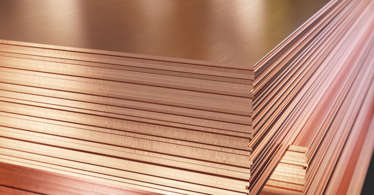
    A close-up view of copper sheets stacked in a warehouse, showing smooth reflective surfaces and rough metal edges.

    Copper sheets for RF shielding are often specified by alloy and thickness before anyone considers how the finished enclosure will come together. The material may offer excellent conductivity, but if forming creates inconsistent seams or poorly controlled openings, the shield can still underperform where electromagnetic energy can find a path.

    The most effective shielding parts aren’t necessarily made from the thickest copper or the highest-conductivity grade. They’re the ones designed with a clear understanding of how the fabricated geometry will affect electrical continuity. That perspective should better guide your evaluation of copper sheet for an RF shielding application.

    Treat the Enclosure as an Electrical Boundary

    A flat copper panel can attenuate electromagnetic energy effectively, but an enclosure only performs as well as its weakest boundary. Openings for connectors or ventilation interrupt the current path, and their effect depends on the geometry relative to the frequencies involved. You therefore need to evaluate these features as part of the shielding design rather than leaving them as routine secondary operations.

    Seams create a similar challenge. Two formed flanges can appear fully closed, yet uneven contact pressure may leave portions of the joint electrically inconsistent. The drawing should identify where reliable metal-to-metal contact is required so the fabricator can protect those surfaces through forming and assembly.

    Select Thickness for Forming Behavior, Not Just Attenuation

    A thicker sheet won’t compensate for a poorly designed joint. Once the wall provides sufficient attenuation for the application, additional gauge may add stiffness without correcting leakage around openings or seams. Thickness still matters, however, because it affects bend force and dimensional stability after forming.

    Thin copper sheets can support compact profiles and detailed features for RF shielding applications, but they may distort when the tooling or bend sequence is poorly matched to the part. Heavier material can hold its shape more readily, although it may complicate tight bends. The useful specification accounts for both the electromagnetic requirement and the geometry that the shop must produce.

    Preserve Contact Through Fabrication

    The quality of copper sheet metal fabrication is most evident at edges and bends, where small dimensional shifts can alter how adjoining parts meet. A flange that falls outside its intended angle may still pass a basic dimensional check, while creating inconsistent electrical contact across the seam. Flatness and mating geometry deserve explicit tolerances when they influence shielding performance.

    Temper selection also affects how the sheet responds during fabrication. A softer condition may form readily, while a harder condition can provide greater stiffness after processing. Neither choice is universally better, so the specification should reflect the bend radius and final assembly method.

    Provide the fabricator with more than the outside dimensions. Show the critical contact zones and note any areas where coatings must not interfere with continuity. The drawing should also identify which joints carry the shielding function, allowing the shop to protect them through cutting and forming.

  4. Aluminum Shims in Precision Robotics Assembly

    July 30, 2026 7:35 pm Comments Off on Aluminum Shims in Precision Robotics Assembly

    A robot’s first argument with its CAD model often happens at a bolted surface. The model shows the faces meet cleanly, yet the actual assembly may reveal a slight tilt once torque is applied. That small shift can greatly affect how a joint tracks, how a sensor reads, or how smoothly the machine returns to the same position. In precision robotics assembly, aluminum shims help you settle those disagreements without redesigning the whole connection.

    Where Real Parts Challenge Perfect Geometry

    Robotics teams spend plenty of time refining motion paths, but the machine still depends on physical contact points behaving as expected. A bracket that sits a few thousandths of an inch too low can change the relationship between a mounted component and the rest of the system. The control package may compensate for some variation, but it shouldn’t have to rescue a mechanical fit that could be corrected at the interface.

    An aluminum shim gives you a measured way to adjust that relationship. Instead of pulling a part into place with fastener pressure, you can support it with the thickness it actually needs. That’s a cleaner fix, and it keeps stress from becoming part of the assembly strategy.

    Stack-Up Control Without Extra Complexity

    Tolerance stack-up has a way of hiding until the parts come together. Each individual component may meet its print, but the combined assembly can still land outside the fit you expected. When that happens, a shim can bring the system back into range without forcing a production delay.

    Aluminum works well here because it adds controlled thickness without adding much mass. That matters a lot in robotic equipment, where weight can influence response during repeated motion. You’re not just filling space; you’re protecting the way the machine moves.

    Why Material Consistency Shapes the Adjustment

    A shim’s value depends on trust. If the material thickness drifts, the correction becomes another source of variation. For prototype builds, it can confuse test results; for production builds, it can slow technicians who need the same adjustment to behave consistently each time.

    This is where sourcing deserves attention. Teams working with aluminum sheet manufacturers need material that supports predictable spacing, especially when a build relies on repeatable shim performance. The shim may be thin, but its thickness has to mean what the drawing says it means.

    Fit Decisions at the Assembly Bench

    A useful shim doesn’t draw attention to itself. It lets a mounted surface sit correctly, helps the fastener load feel more controlled, and gives the technician a practical way to make a precise correction. When it comes to precision robotics assembly, the quiet adjustments that aluminum shims provide can keep the build moving while preserving the intent behind the design.

  5. Stainless Steel for Battery Thermal Management

    July 14, 2026 3:23 pm Comments Off on Stainless Steel for Battery Thermal Management

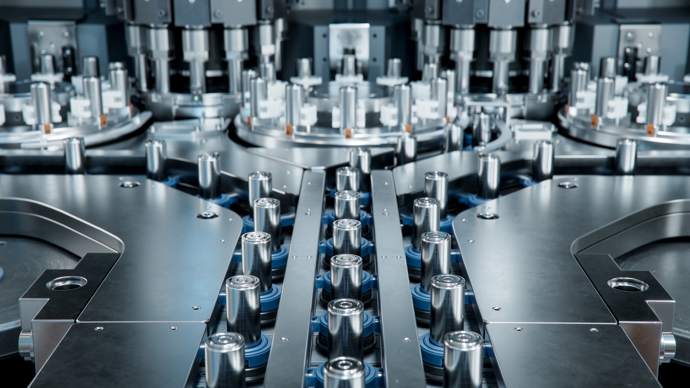
    Rows of cylindrical battery cells arranged on a conveyor inside an automated industrial production line.

    Battery thermal management is one of the quieter engineering challenges driving innovation across industries right now. In high-stakes battery applications, thermal stability under load can make or break performance. That’s why more engineers are turning to stainless steel for battery thermal management. It can provide improved cooling solutions that meet the demands of a variety of advanced power systems.

    Why Stainless Steel Specifically?

    The short answer is that it checks a lot of boxes at once. Stainless steel handles heat well, resists corrosion, and holds up under the kind of mechanical stress that thermal cycling puts on materials over time. When it comes to battery thermal management specifically, those properties translate into better performance and fewer failure points in the overall system, leading to longer service lifespans.

    Heat Exchangers and Cooling Plates

    One of the most common applications of stainless steel in battery thermal management is in heat exchangers and cooling plates. This steel’s thermal conductivity, while not as high as copper or aluminum, is more than adequate when paired with a well-designed flow channel geometry.

    Chemical etching companies have become key players here because etching allows for incredibly precise, micro-scale channel patterns that maximize surface contact without adding bulk or weight. That level of precision is tough to match with conventional machining methods.

    Stamped Components and Aerospace

    For stamping parts manufacturers, thin-gauge stainless steel is a compelling choice for cell-level thermal interface components. That’s due to the fact that these teams can form complex geometries with tight tolerances, and the material’s natural resistance to oxidation means you’re not introducing long-term reliability risks into battery packs expected to last a decade or more.

    Aerospace applications take this even further, since weight savings and thermal stability both matter enormously in airborne or space-bound systems. Not many other materials can hold up against such restrictions.

    Medical Devices

    Medical device makers are also finding stainless steel components increasingly attractive in thermal management, especially as portable and implantable devices incorporate higher-capacity battery systems. Biocompatibility, sterilizability, and dimensional stability under varying temperatures all work in stainless steel’s favor, making it a natural fit for applications where material performance is non-negotiable.

    Keeping Up with Battery Demand

    It’s worth noting that stainless steel sales in the precision components sector have grown steadily alongside the battery industry itself, and it’s not hard to see why. As battery packs become denser and more energy-intensive, the thermal demands on surrounding components rise with them, and stainless steel is one of the few materials that scales gracefully with those demands.

  6. Precision Slitting for Thin Metal Prototypes

    June 26, 2026 6:48 pm Comments Off on Precision Slitting for Thin Metal Prototypes

    A CNC laser cutting metal at close range, with bright sparks coming off of it. The metal sheet looks relatively clean.

    Prototypes rarely give you room to “figure it out later.” When a part depends on thin metal, the material must meet the required width and edge quality before the first test ever begins.

    Precision slitting is the process that helps engineers and manufacturers move from concept to sample without wrestling with oversized stock or rough, inconsistent strips. If you want to learn how precision slitting can help with your thin metal prototypes, this quick guide is here to help.

    Why Slitting Matters Early in Development

    Prototype work often moves fast, but speed doesn’t help much when the material isn’t usable. A strip that’s too wide can slow down tooling trials. A strip that varies across the coil can skew results before anyone knows whether the design itself works.

    Precision slitting gives teams tighter control before production decisions get expensive. Instead of adapting the prototype around available stock, manufacturers can test with material that reflects the intended final part more closely.

    That matters for thin gauges, where small differences can feel much larger in the finished component. A slight width issue might affect how material feeds through equipment or how parts nest during forming.

    Better Fit for Specialized Applications

    Thin metal prototypes often serve demanding applications. Aerospace parts depend on materials that behave predictably, and the same pressure shows up in medical components, etched pieces, precision washers, and similar thin metal work. When the strip width stays consistent, teams can focus on performance instead of compensating for material problems.

    Slit-to-width metal also helps when a prototype uses specialty alloys or a thin copper sheet. These materials may require careful handling because surface damage or edge distortion can affect the next step in the process.

    Cleaner Testing With Less Waste

    Prototype teams don’t always need a large order. They need material that supports accurate testing without creating a pile of unused stock. Custom slitting helps reduce excess by matching the metal to the project instead of forcing the project to match standard inventory.

    This aspect of precision slitting for thin metal prototypes can make early-stage testing much more practical. Engineers can run samples and adjust the design with less material sitting on the shelf afterward.

    What to Look for in a Slitting Partner

    A good slitting partner understands that prototype work doesn’t always follow a predictable path. One job may need a tight tolerance for a small component, whereas another may require a quicker turnaround because the test window keeps moving.

    When it comes to thin metal prototypes, you’ll want a supplier that can handle narrow widths while maintaining quality and responsiveness, without making the process feel overly complicated. As you near the end of a prototype timeline, be sure to find a steel and metal sales near you that truly understands precision thin metal from the start.

  7. Smart Inventory Solutions for Custom Slit-to-Width Metals

    May 15, 2026 4:20 pm Comments Off on Smart Inventory Solutions for Custom Slit-to-Width Metals

    A close-up view of a metal roller cutter slicing a shiny sheet into narrow strips as it moves through the machine.

    Inventory issues don’t always look dramatic at first. A coil sits longer than expected because it’s wider than the next job needs. A sheet gets trimmed more than planned before it reaches production. Over time, those small mismatches can create delays that no one wants to explain during the next meeting covering the schedule.

    Custom slit-to-width metals help manufacturers develop smarter inventory solutions by keeping inventory closer to actual production demand. Instead of buying oversized materials and adapting them later, teams can order metal that’s already closer to the required width.

    Match Material to the Work

    Smart inventory starts with material that fits the job. Standard stock can cover broad needs, but it often creates extra handling when a project calls for a specific width. That extra step may seem minor until it repeats across multiple orders.

    Slit-to-width metals reduce that friction. They give purchasing teams greater control over what comes into the shop and help production teams start with materials ready for the next stage. For repeat parts, that consistency can make planning much easier.

    Reduce Waste Before It Starts

    Waste doesn’t always show up in the form of discarded scrap. Sometimes it comes to you as leftover strips that stay on the shelf because they feel too useful to toss. Other times, it’s partial sheets that don’t quite fit the next order.

    Regardless of the form, custom slit-to-width ordering helps reduce that problem before it even begins. A shop using thin copper sheets for etched components, for example, can limit unnecessary trimming by ordering closer to the needed width. Less trimming means fewer offcuts and less time spent managing material that may never get used.

    That kind of control also supports cleaner inventory records. When the material sizes you’ve chosen directly link to your active jobs, teams can track usage with greater confidence. Plus, reordering becomes less reactive because buyers can see what the shop actually uses.

    Keep Production Moving

    Inventory planning isn’t only about what sits on the shelf. It’s also about how quickly the right material can move into production when a job opens. If stock needs extra processing before anyone can use it, it’s not as available as it might seem.

    A consistent custom slit-to-width metal supply helps improve your inventory by reducing that gap. Teams can plan around material that arrives closer to the required form, which helps scheduling stay realistic. It also keeps buyers from overstocking just to cover sizing uncertainty. For manufacturers working with tight timelines, that kind of flexibility matters.

  8. The Impact of Material Science on Aerospace Certification

    May 7, 2026 5:17 pm Comments Off on The Impact of Material Science on Aerospace Certification

    A fighter jet engine cross-section showing turbine blades, bearings, and aerospace hardware all at once.

    Due to the nature of the industry, aerospace parts face careful review long before they ever reach an aircraft. Every material choice has to support safety while giving engineers a clear reason to trust the finished part. Certification doesn’t begin at the final inspection. It starts with the metal itself, which is what makes material science a major force in aerospace certification.

    Material Behavior Guides Approval

    Certification teams need proof that a material can withstand real flight conditions. Heat shifts, vibration, and repeated stress can all change how a metal performs over time. When a material reacts in an unpredictable way, the part becomes harder to approve.

    Material science helps engineers predict that kind of behavior before production moves too far along. Both alloy choice and thickness control affect how a part handles stress. When teams understand those limits early, they can design with fewer certification surprises.

    Consistency Builds Trust

    A material doesn’t just need to perform well once. It needs to perform the same way from one batch to the next. Aerospace certification depends on repeatable results, so small changes in metal properties can slow down the review process.

    This is where tight material control matters. For example, thin aluminum sheets used in aerospace components may need precise thickness and dependable formability. When suppliers maintain those traits consistently, manufacturers can document performance with greater confidence.

    Testing Turns Data Into Evidence

    Another major impact of material science on aerospace certification is that it gives testing a clearer purpose. Engineers don’t test parts at random; they measure how the metal should perform under the conditions it’ll face. Strength tests and fatigue studies help show whether the part can meet its required limits.

    That evidence matters during certification. If the test data matches the expected material behavior, the approval process becomes more straightforward. If it doesn’t, engineers can trace the issue back to the material choice or the manufacturing process.

    Design Depends on Material Limits

    Aerospace design often asks metal to do more while weighing less. Material science helps engineers decide where they can reduce thickness and where they need more support. It also shows how far a material can bend or stretch before performance drops.

    Those choices affect certification because every design feature needs a technical reason behind it. A lightweight part still has to prove it can survive its working environment. When material data supports the design, reviewers have a clearer path to approval.

  9. Balancing Recyclability and Performance in Metal Design

    April 21, 2026 1:44 pm Comments Off on Balancing Recyclability and Performance in Metal Design

    Two women looking at a couple of monitors that show the mechanisms of a metal part. One of them is holding the actual part.

    Metal design rarely gives you the luxury of pursuing a single priority at a time. There are many aspects you need to keep in mind when it comes to the design process. For example, engineers and buyers need parts that hold up in real use while still making sense when material recovery matters. That tension that sits at the center of this, balancing recyclability and performance in metal design, is what we’re here to look at in this quick guide.

    Why Material Choice Gets Complicated

    While a certain metal may seem like the right fit at first, it may create undesirable tradeoffs once production begins. Performance in this area depends on how the material behaves during forming and how it holds up against corrosion. Recyclability adds another layer because recovery only helps when the part still meets the demands of the job.

    That’s especially true in aerospace and medical work, where reliability carries real weight. Designers can’t treat recyclability as a bonus if it weakens the final part. At the same time, they can’t ignore how material waste affects efficiency over the life of a project.

    Performance Still Sets the Standard

    In demanding applications, performance must drive the decision. A gasket has to seal correctly. A shim must maintain its dimensions. A stamped or etched component has to meet the exact needs of the assembly.

    However, that doesn’t push recyclability out of the discussion. It just means teams should judge it based on actual use rather than broad assumptions. The better approach starts with how the alloy performs in fabrication and service, then weighs how well it supports recovery after that.

    Recyclability Starts With Better Planning

    The smartest way to improve recyclability while balancing it with performance in metal design is to build it into the process from the start. Teams can reduce waste by choosing the right gauge and by avoiding overly broad specifications. They can also improve yield by ordering material in sizes that better match the part.

    Supplier support plays a big role here. A dependable stainless steel sheet supplier, for example, can help buyers source material that fits the application more closely, reducing scrap before production ramps up. That kind of planning makes recyclability a practical design choice instead of an afterthought.

    Good Design Focuses on the Full Lifecycle

    Strong metal design doesn’t lean too hard in one direction. It looks at how the material will be processed, how the part will perform in use, and how efficiently the leftover material can move back into the stream. That wider view leads to smarter decisions at the specification stage.

    When teams strike that balance, they get parts that perform consistently and use material more effectively. For manufacturers working with thin-gauge metals, that balance often separates a merely workable design from one that supports both production goals and long-term efficiency.

  10. Corrosion Resistance Testing Standards in Modern Alloys

    April 17, 2026 4:24 pm Comments Off on Corrosion Resistance Testing Standards in Modern Alloys

    A gloved finger pointing at some rust on the side of a car. The metal that's rusting is right over the wheel.

    When you’re evaluating modern alloys, you can’t reduce corrosion resistance to one simple test result. Different standards exist because different materials face different corrosion risks, and each test is designed to measure something specific. Once you understand what those standards actually cover, it becomes much easier to compare alloys and choose the right material for the job. To do that better, here’s a quick look at some corrosion resistance testing standards in modern alloys.

    ASTM B117: Salt Spray Testing

    ASTM B117 is still the corrosion test most people recognize first because it creates a controlled salt spray environment and gives manufacturers a common baseline. It outlines the equipment, procedures, and exposure conditions needed to run the test consistently, which is why it appears so often in thin sheet metal material discussions and product specs. At the same time, B117 doesn’t tell you everything by itself. It doesn’t automatically define the right specimen, the right duration, or what the result should mean for every alloy and application.

    ASTM G48: Pitting and Crevice Corrosion

    When the real concern is pitting or crevice corrosion, ASTM G48 gives you a much more targeted way to evaluate performance than a broad salt spray test. This standard is commonly used for stainless steels and related alloys, especially when chloride exposure could trigger localized attack. Instead of focusing on general surface corrosion, G48 focuses on the types of damage that can cause serious problems even when the rest of the material still looks fine. That makes it especially useful when you need to separate alloys that seem similar on paper but won’t behave the same way in service.

    ASTM A262: Intergranular Corrosion

    ASTM A262 is a corrosion resistance testing standard for modern alloys because intergranular corrosion isn’t always obvious until the material has already been affected by processing or heat exposure. Rather than relying on a single method, A262 includes multiple practices used to detect susceptibility to intergranular attack in austenitic stainless steels. That makes it more nuanced than a broad screening test, but it also makes it more valuable when you need a closer look at stainless performance. If you’re evaluating material that’s been welded, heat-treated, or otherwise processed, this standard helps you understand whether those steps changed its corrosion behavior.

    ASTM G34: Exfoliation in Aluminum

    ASTM G34 addresses a very different problem: exfoliation corrosion in high-strength aluminum alloys, especially 2XXX and 7XXX series products. This kind of attack can be especially relevant in wrought aluminum used in harsh outdoor or industrial environments, where corrosion can spread in layers and undermine long-term performance. That’s why G34 matters in ways a stainless-focused test never could. You can’t swap corrosion standards from one alloy family to another and expect a useful answer, because aluminum and stainless don’t fail under the same conditions or for the same reasons.

Address 5721 Schaefer Avenue
Chino, CA 91710
T: 909-393-2273 F: 909-393-2811
Email: Sales@ThinMetalSales.com
Links
  • Home
  • Privacy Policy
  • Terms of Service
  • Sitemap
© 2026 Thin Metal Sales , All Rights Reserved Site created by Thomas Marketing Services